Hysys aspen mac Aspen hysys process flow diagram B: hysys process flow diagram for 3-stage (case b) membrane integrated
Aspen HYSYS process flow diagram for the steady-state simulation of
Aspen hysys process flow diagram of dme production via reactive Process flow diagram and aspen hysys model for case study 3. Hysys adjust
(a) section 1-reformer section aspen hysys ® process flow diagram; (b
Aspen hysys simulation teng adaptedHysys process flow diagram for a 300 mw hte plant with air sweep Hysys aspenAspen hysys process flow diagram used for heat-balance analysis.
Process flow diagram for initial condition (hysys)Aspen hysys process flow diagram Hysys process flow diagram of the thermal power plant.Hysys aspen.

Hysys aspen modelled
Process flow diagram of simulation in aspen hysys (adapted from teng etHysys simulation aspen ashaka 1. process flow diagram of the modelled base case in aspen hysysAspen hysys process flow diagram used for heat-balance analysis.
Aspen hysys flow-sheet of standard processPlant process flow diagram simulated in hysys.processtm. Hysys process simulation aspen flow capture diagram cement ashaka unit plantProcess flowsheet developed and simulated in aspen hysys..

Hysys n 2 extraction process flow diagram
Aspen hysys based simulation of processProcess flow diagram for hysys simulation Aspen hysys configurationsMembrane hysys integrated gas.
Aspen hysys flow sheet of base case process configurationsHysys process flow diagram of ammonia synthesis Hysys thermalAspen hysys.

Aspen hysys process flow diagram for the steady-state simulation of
Aspen hysys process flow diagram for cryogenic biogas upgradingAspen hysys process flow diagram Aspen hysys simulation process flow diagram for the selexol captureAspen hysys process flow diagram for the steady-state simulation of.
Process flow diagram and aspen hysys model for case study 1.Hysys synthesis ammonia Hysys tutorial : set, adjust and case study (part 6)The aspen hysys ® process flow diagram of the developed gtl process.

Simulated hysys
The aspen hysys ® process flow diagram of the developed gtl processProcess flow diagram and aspen hysys simulated case study for the lpg Aspen hysys simulation process flow diagram for the selexol captureDiagram mw hte hysys sweep.
Hysys process flow diagram for a 300 mw hte plant with no sweep .


HYSYS process flow diagram of the thermal power plant. | Download

The Aspen HYSYS ® process flow diagram of the developed GTL process

Aspen HYSYS process flow diagram for cryogenic biogas upgrading

Process flow diagram for initial condition (HYSYS) | Download
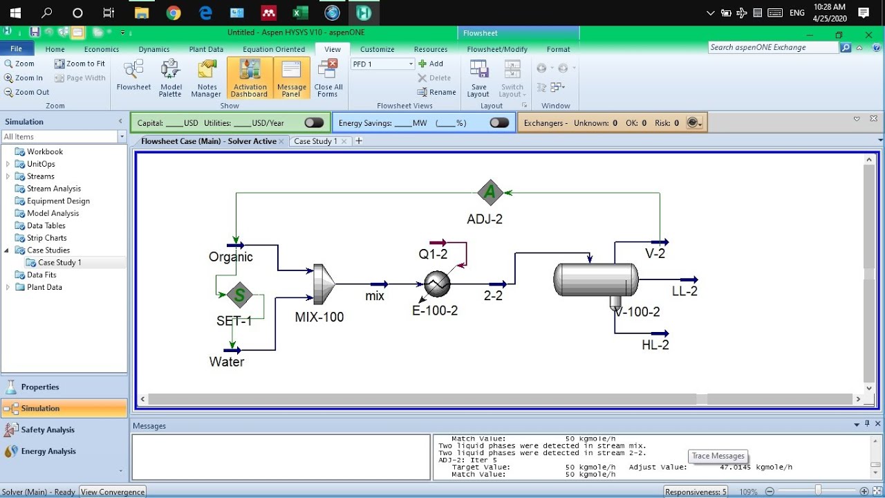
HYSYS Tutorial : Set, Adjust and Case Study (Part 6) - YouTube

Aspen HYSYS process flow diagram for the steady-state simulation of

Aspen Hysys Process Flow Diagram | Download Scientific Diagram